Ellduino development environment
The Ell-duino development environment consists of the Ellduino development board and the Ellduino extension to the Arduino IDE. Alternatively, it is also possible to write code for the Ellduino board using GCC; see the Gcc detailed tutorial.
In a most typical case, an Arduino Shield or a breadboard is connected to the Ellduino development board, the combination is connected with an Ethernet cable to a Power-over-Ethernet switch, hub, or injector, and the PoE switch/hub/injector is somehow connected to the Internet. Figure 1 below illustrates a basic setting with a breadboard and switch connected to the Digital input D2.
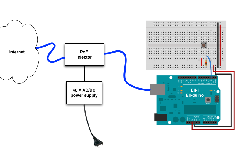
Figure 1: Basic Ellduino setting
In the setting of Figure 1, the Ellduino board is connected with a single Ethernet cable to the PoE power injector. This cable carries both electric power (currently up to some 60 Watts) and digital data. According to the PoE standards, the cable may be up to 100 meters long. Hence, the Ellduino board (and any other Ell-i node) may be placed quite far from the PoE switch, hub, or power injector.
Building a new Ell-i application usually involves both hardware and software development. The first round of any hardware development typically takes places on a breadboard, either as a separate one as shown in Figure 1, or on a smaller breadboard glued to an Arduino prototyping shield. The successive rounds may then involve soldering the prototype on a prototyping shield, TBD